By all accounts, our iBrite RGB CPU April Fool’s gag was a roaring success. We can’t thank our community enough for all the great feedback, and for sharing in a joke that was, speaking personally, a lot of fun to make. Also, we’re honored to have been featured on a number of sites’ 2019 April Fools roundups, including The Verge, Tom’s Hardware, Australian Lifehacker, PCGamesN, Android Central, and The Washington Post (even though they’re not big fans of the holiday), not to mention all the shoutouts on Reddit, Twitter, and Facebook.
We’ve gotten a few comments from folks interested in how we made the iBrite, since no, Newegg didn’t secretly invest the -illions it would take to create or rent out a semiconductor foundry or whatever equipment. Despite claiming we had made the world’s first CPU in the PetaHertz range, in reality the bulk of the project was just gluing an Arduino-powered LED matrix to a dead Core i7.
Well, okay. There’s a little bit more to it than that.
Wiring the iBrite
 Before I did anything else, I had to make sure the Adafruit dot-matrix worked, and that meant wire soldering. Adafruit has some info on wiring up their matrices, but not for the specific model we used.
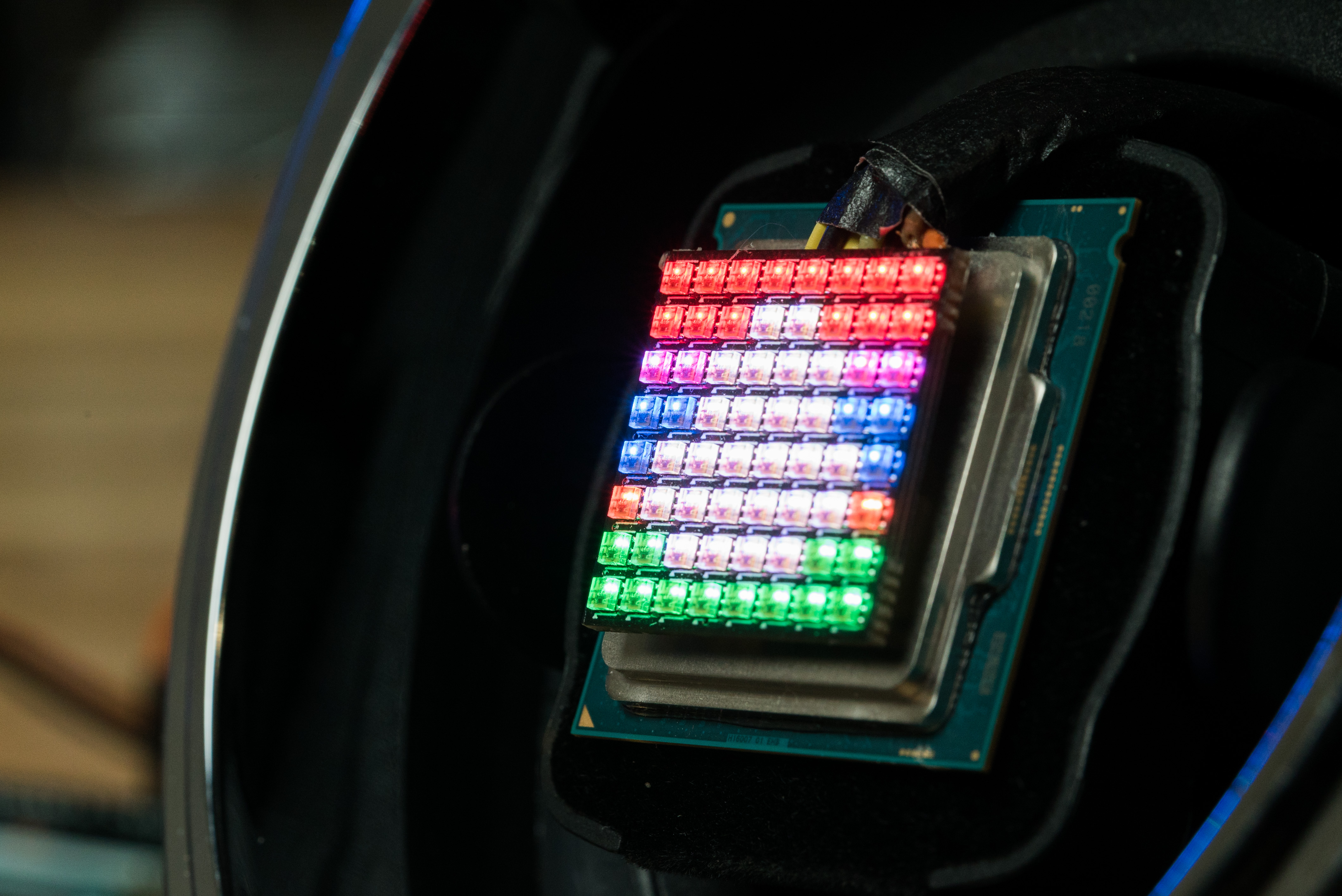
In a nutshell, the Adafruit DotStar High Density 8×8 Grid matrix I used has 10 contact points on the underside of the LEDs:
- Set of four “in” points: Clock In, Data In, 5V+ and GND.
- Set of four “out” points: Clock Out, Data Out, 5V+ and GND.
- An additional pair of 5v+ and GND points.
Each set of four pins in on an edge of the matrix’es PCB, and there are two more power supply pins in the center. The four “in” pins need to be connected to the Arduino, and according to Adafruit’s documentation, the two power supply pins need to be linked to an independent power supply somehow. (Which is an issue that comes up in a little bit.) The other four “out” pins are only there for connecting multiple matrices in sequence, and can be ignored otherwise.
I started by loading an Arduino Uno R3 with a diagnostic script for the matrix that Adafruit publishes, and then linking and powering the matrix through a breadboard, including the power supply terminals. Once I knew my soldering job was good and that I had all the wires connected, I turned the Arduino back on and watched the matrix light up. I was good to go! …In breadbox form.
Trying to rig the prop CPU for photography with loose jumper wires hooked to a breadboard was going to be a pain, to say the least. I also knew conclusively that I didn’t want to run separate power supplies for both the Arduino and the Matrix. That would make shooting messier, and I wanted to avoid it if possible. (And also I forgot to order a screw terminal power supply or adapter.)
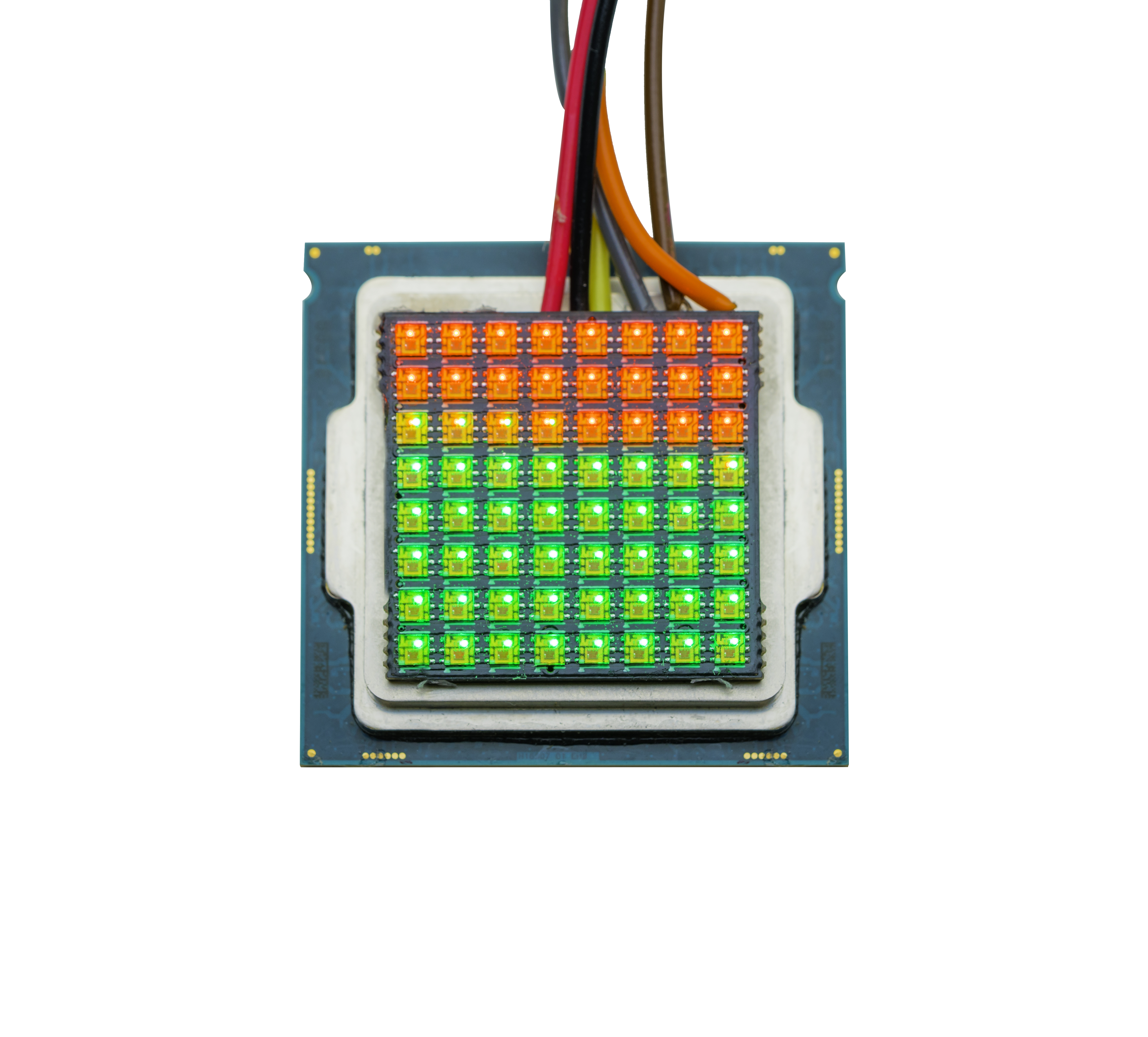
Fortunately, the wire splicing for that wasn’t too difficult. Essentially, I twisted together both pairs of GND and 5V+ wires and crimped each pair into a pin connector before jamming them into a plastic pin housing. This way, each pair of wires could “share” the 5V and GND pins on the Arduino. I’m happy to report that this worked flawlessly, and I didn’t end up needing any other power supplies beyond the USB brick I used to power the Arduino itself. After that, all I had to do was apply some heat-shrink to the wires, just for a cleaner look. I should also note that I made some extension cables, just for the purposes of rigging the iBrite prop for shooting.
Making it Shiny
The animation you see in the April Fool’s video is more or less that same diagnostic script I mentioned, with a few tweaks concerning animation speed and LED brightness. It’s part of the library that Adafruit offers for its DotStar products, and compiled and ran easily enough. It wasn’t the prettiest option, but we had to hit that April first deadline, so we took the “quick n’ dirty” approach to some aspects of this project.
For the static Egg images, well, I did it the hard way by entering in color values for each of the 64 LED’s. I’m sure someone far more fluent with the Arduino IDE could do this far more efficiently, but I did the best I could for my experience level with Arduino syntax.
Building a CPU
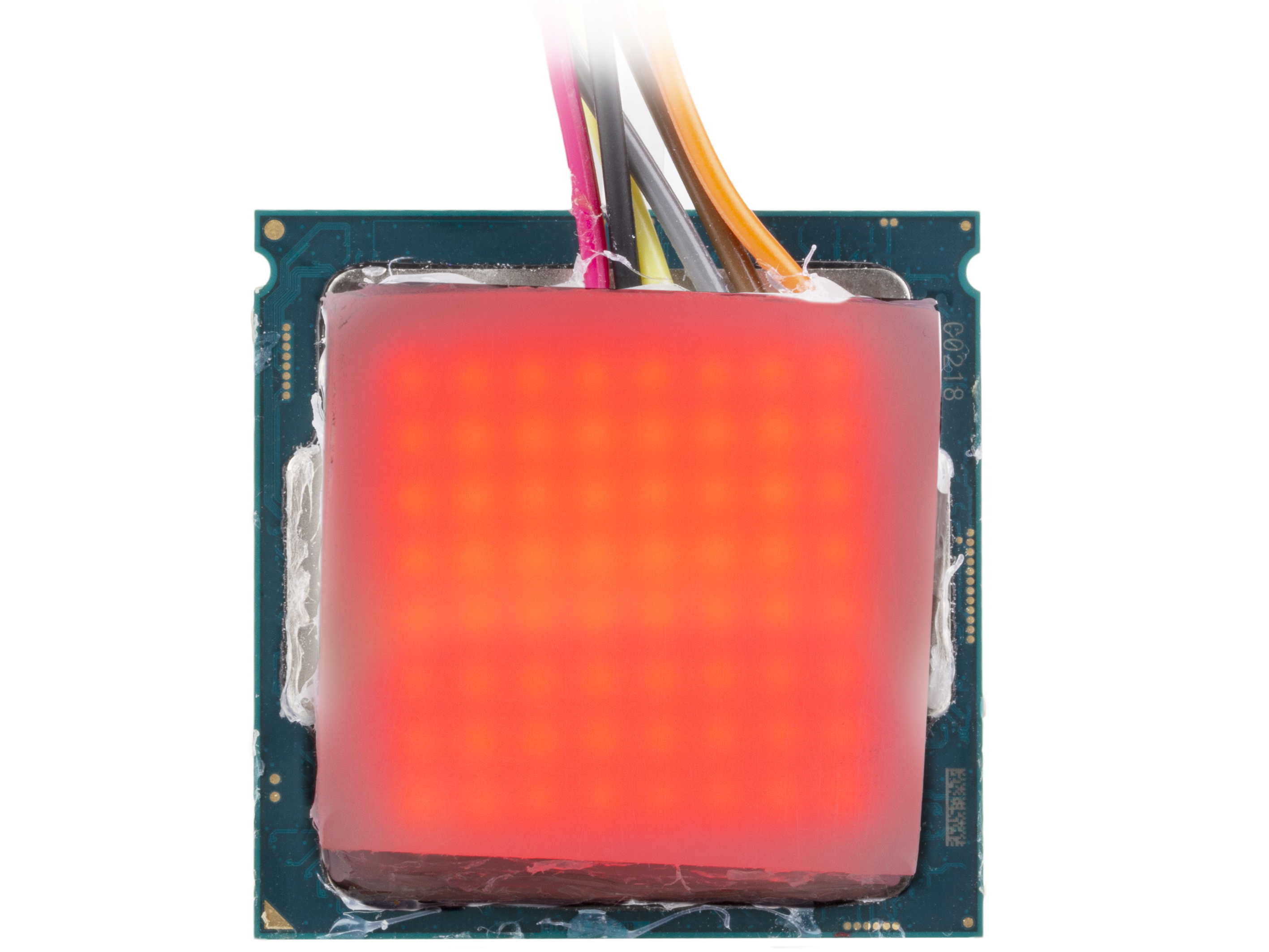
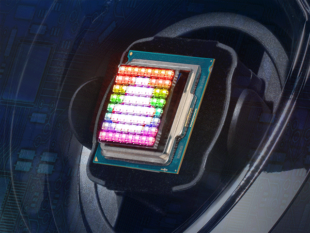
With the iBrite now functionally sound, it was time to dress it up as a “real” CPU. All I really wanted was something that would fit in an LGA 1151 socket and light up. So I decided to mount the DotStar matrix to an old, dead, Core i7. Mind you, this was an almost 4 year old 6700k that had been well used and abused, not a new 9700k that had lemoned out on us, because that would be highly unusual.
My first attempt involved hot glue. A lot of hot glue, as you can see in the picture above. I also glued on a janky acrylic diffuser I cut with a Dremel. At this point, the jank was supposed to be part of the joke.
“We know this looks like distilled butt, but we’re gonna straight face it anyway.”
As funny as I thought that was, we ultimately settled on a cleaner style for the iBrite. The joke was now “Wait, could this be a real thing?” So we had a new, laser cut diffuser made, which you can see below:
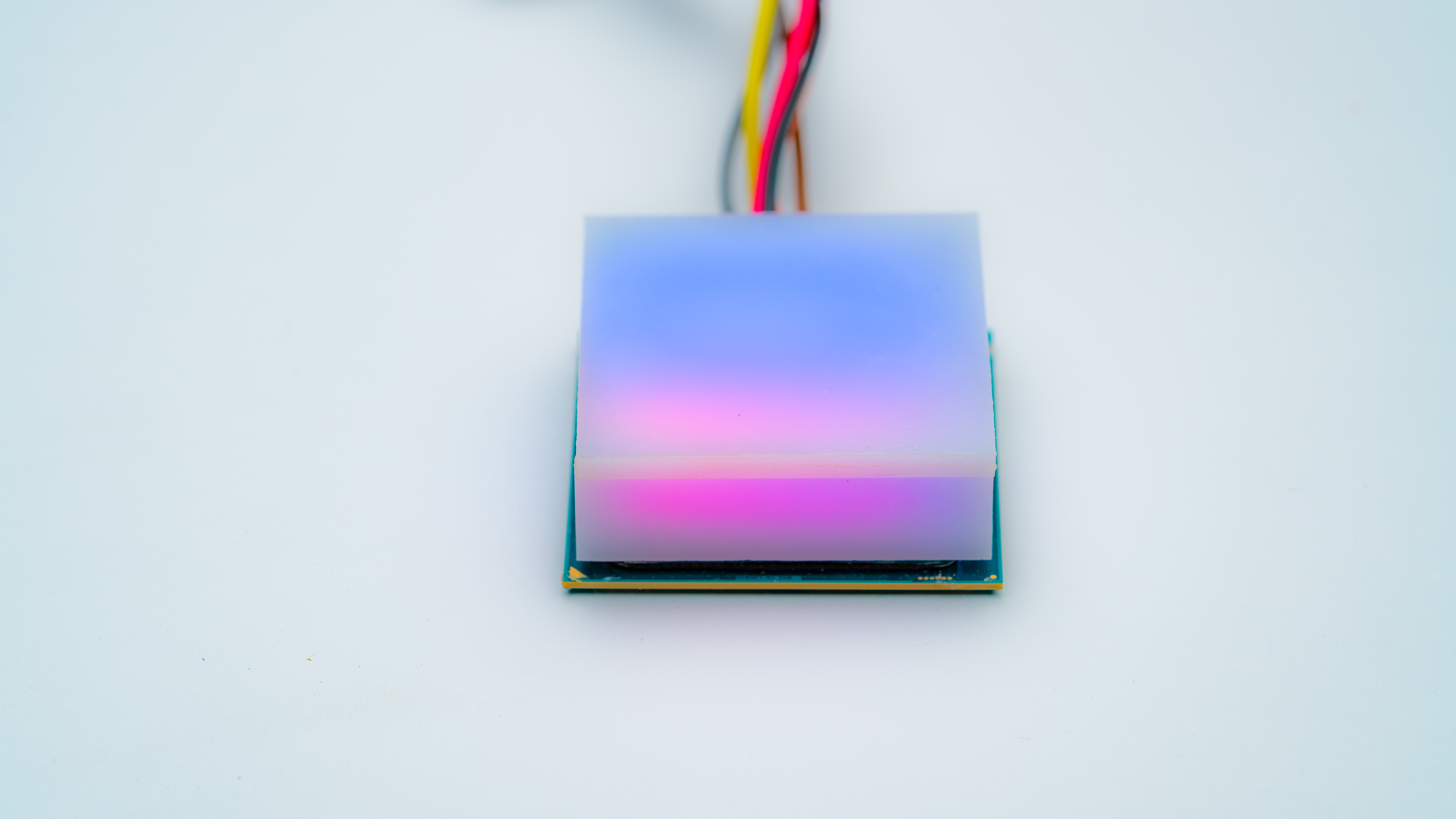
Unfortunately this version also had some problems. While personally felt that it was the nicest looking actual product, it had some structural issues that couldn’t be fixed with hot-glue alone, and there were concerns that it didn’t look “enough” like an actual CPU. So the idea of a diffuser was scrapped entirely, leading to the final result we released on April 1st.
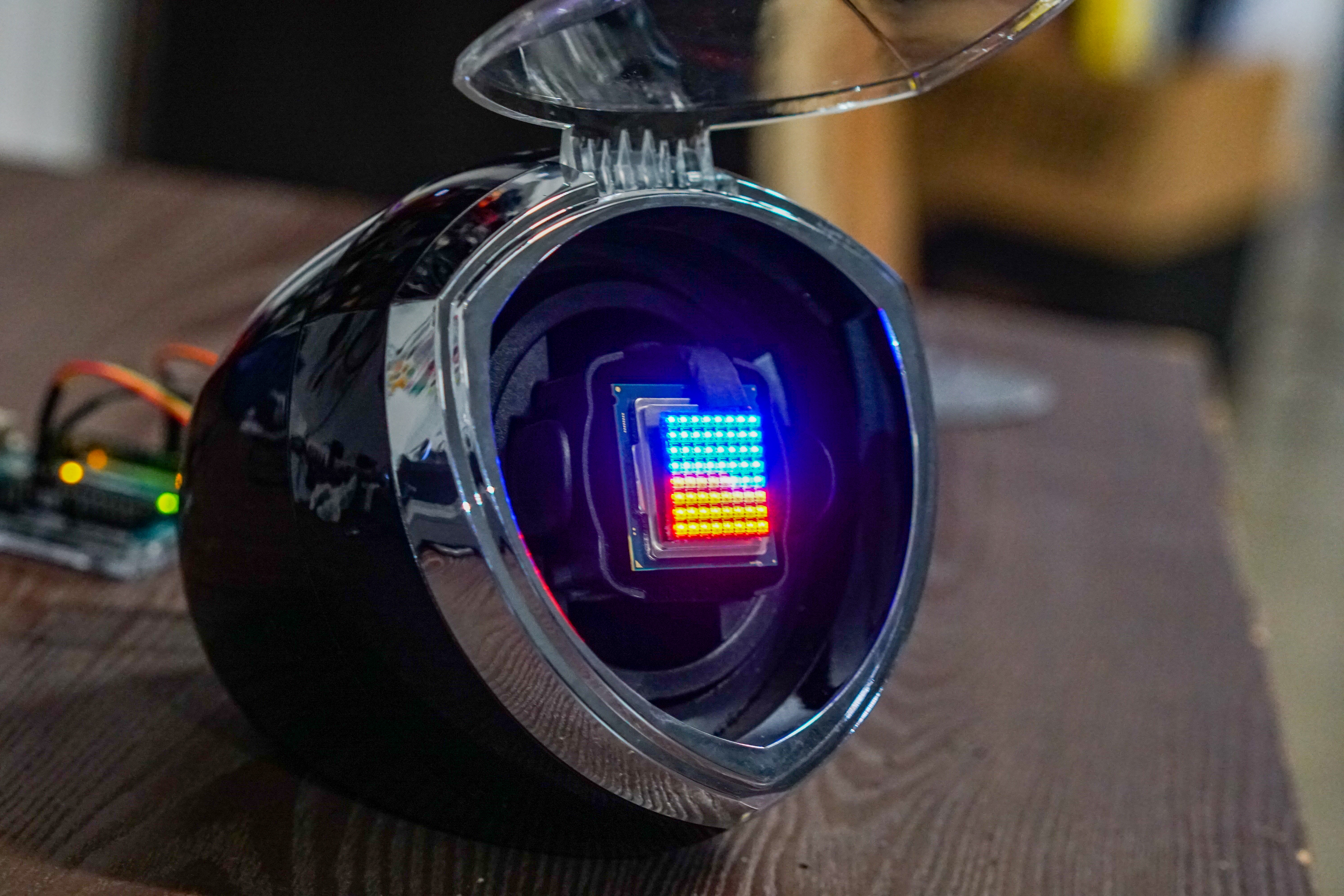
Time to Shine
With the iBrite working as intended, it was time to write some jokes and get our creation camera-ready. With construction done, I passed the prop over to our camera crew and video editors, who put together the video you (hopefully) enjoyed earlier this month.
And that’s pretty much it. While making a CPU light up isn’t so hard, I think we’ll still leave all the heavy lifting to AMD and Intel.
Related Posts
- Best CPUs for Gaming and Productivity in 2026: Intel vs AMD Showdown
- Should You Buy an Unlocked CPU in 2026? A Practical Guide for Every Type of Builder
- Unlocked vs. Locked CPUs Explained: What the “K” Really Means in 2026
- Do You Actually Need a Xeon or Threadripper? A 2026 Workload Guide to Choosing the Right CPU Platform
- Desktop CPU vs. Server CPU: What’s Actually Different Under the Hood in 2026